Unity中的shadows(四)collect shadows
本文是Unity中的shadows系列的最后一篇文章。上一篇文章主要介绍了阴影接收的内容,这一篇文章来看下之前跳过的creen space shadow map下的阴影收集过程。
阴影收集
平行光源下使用screen space shadow map时,unity会进行一次阴影收集的行为。通过frame debug我们可以看到:

Unity使用了一个名为Internal-ScreenSpaceShadows的shader进行处理,幸运的是,这个shader是开源的,可以在unity官网上下载到。整个shader代码有400多行,这里就不完整贴出来了,只截取一些需要分析的代码段。
首先注意到这个shader有4个subshader,分别处理软阴影和硬阴影:
// ----------------------------------------------------------------------------------------
// Subshader for hard shadows:
// Just collect shadows into the buffer. Used on pre-SM3 GPUs and when hard shadows are picked.

SubShader {
    Tags{ "ShadowmapFilter" = "HardShadow" }
    Pass {
        ZWrite Off ZTest Always Cull Off

        CGPROGRAM
        #pragma vertex vert
        #pragma fragment frag_hard
        #pragma multi_compile_shadowcollector

        inline float3 computeCameraSpacePosFromDepth(v2f i)
        {
            return computeCameraSpacePosFromDepthAndVSInfo(i);
        }
        ENDCG
    }
}

// ----------------------------------------------------------------------------------------
// Subshader for hard shadows:
// Just collect shadows into the buffer. Used on pre-SM3 GPUs and when hard shadows are picked.
// This version does inv projection at the PS level, slower and less precise however more general.

SubShader {
    Tags{ "ShadowmapFilter" = "HardShadow_FORCE_INV_PROJECTION_IN_PS" }
    Pass{
        ZWrite Off ZTest Always Cull Off

        CGPROGRAM
        #pragma vertex vert
        #pragma fragment frag_hard
        #pragma multi_compile_shadowcollector

        inline float3 computeCameraSpacePosFromDepth(v2f i)
        {
            return computeCameraSpacePosFromDepthAndInvProjMat(i);
        }
        ENDCG
    }
}

// ----------------------------------------------------------------------------------------
// Subshader that does soft PCF filtering while collecting shadows.
// Requires SM3 GPU.

Subshader {
    Tags {"ShadowmapFilter" = "PCF_SOFT"}
    Pass {
        ZWrite Off ZTest Always Cull Off

        CGPROGRAM
        #pragma vertex vert
        #pragma fragment frag_pcfSoft
        #pragma multi_compile_shadowcollector
        #pragma target 3.0

        inline float3 computeCameraSpacePosFromDepth(v2f i)
        {
            return computeCameraSpacePosFromDepthAndVSInfo(i);
        }
        ENDCG
    }
}

// ----------------------------------------------------------------------------------------
// Subshader that does soft PCF filtering while collecting shadows.
// Requires SM3 GPU.
// This version does inv projection at the PS level, slower and less precise however more general.

Subshader{
    Tags{ "ShadowmapFilter" = "PCF_SOFT_FORCE_INV_PROJECTION_IN_PS" }
    Pass{
        ZWrite Off ZTest Always Cull Off

        CGPROGRAM
        #pragma vertex vert
        #pragma fragment frag_pcfSoft
        #pragma multi_compile_shadowcollector
        #pragma target 3.0

        inline float3 computeCameraSpacePosFromDepth(v2f i)
        {
            return computeCameraSpacePosFromDepthAndInvProjMat(i);
        }
        ENDCG
    }
}
vertex shader
可以看到,这4个subshader所用到的vertex shader代码是同一份,来看一下它关键部分的实现:
struct appdata {
    float4 vertex : POSITION;
    float2 texcoord : TEXCOORD0;
    float3 ray : TEXCOORD1;
};

v2f vert (appdata v)
{
    v2f o;
    float4 clipPos;

    clipPos = UnityObjectToClipPos(v.vertex);

    o.pos = clipPos;
    o.uv.xy = v.texcoord;

    // unity_CameraInvProjection at the PS level.
    o.uv.zw = ComputeNonStereoScreenPos(clipPos);

    // Perspective case
    o.ray = v.ray;

    // To compute view space position from Z buffer for orthographic case,
    // we need different code than for perspective case. We want to avoid
    // doing matrix multiply in the pixel shader: less operations, and less
    // constant registers used. Particularly with constant registers, having
    // unity_CameraInvProjection in the pixel shader would push the PS over SM2.0
    // limits.
    clipPos.y *= _ProjectionParams.x;
    float3 orthoPosNear = mul(unity_CameraInvProjection, float4(clipPos.x,clipPos.y,-1,1)).xyz;
    float3 orthoPosFar  = mul(unity_CameraInvProjection, float4(clipPos.x,clipPos.y, 1,1)).xyz;
    orthoPosNear.z *= -1;
    orthoPosFar.z *= -1;
    o.orthoPosNear = orthoPosNear;
    o.orthoPosFar = orthoPosFar;

    return o;
}
v2f保存了要传递给fragment shader的信息,其中pos表示当前相机投影剪裁空间的位置,uv存储了顶点的纹理坐标和屏幕坐标。这个ray分量却是一个没见过的新鲜东西,它代表当主相机是透视相机时(注意当前相机和主相机不是一回事),从相机位置到远剪裁面顶点的射线,可以理解为是构成相机视锥体的4条射线。这么一说,仿佛传给vertex shader的顶点数量就只有4个一样。实际上呢,的确如此。
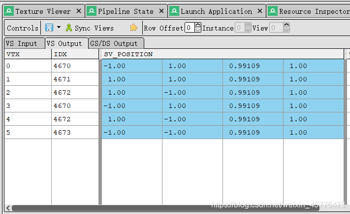
怎么验证呢?unity本身并没有提供给我们查看传给vertex shader顶点信息的工具。不过不要紧,我们可以使用RenderDoc,截帧查看:

6个index,恰好就是两个三角形,也就是4个顶点。可以看到传入的position其实就是屏幕的4个顶点坐标,TEXCOORD1就是上面提到的ray分量。这个ray是怎么算的呢?首先我们的camera组件的fov是60度,近裁剪面是0.3,远裁剪面是1000:

ray的z分量就可以立刻求出。如果要求xy,我们还需要知道当前camera的aspect,可是camera组件并没有,这时可以从frame debug中捞一捞,看一下camera渲染的depth texture的尺寸是多少:

这样aspect的值就显然了:
a
s
p
e
c
t
=
w
h
=
1141
529
aspect =\dfrac{w}{h} = \dfrac{1141}{529}
aspect=hw?=5291141?
由于我们的fov是vertical的,所以优先求出远裁剪面的高度:
h
=
z
f
?
t
a
n
θ
=
1000
×
3
3
=
577.35
h = z_f \cdot tan \theta = 1000 \times \dfrac{\sqrt 3}{3} = 577.35
h=zf??tanθ=1000×33??=577.35
进而远裁剪面的宽度:
w
=
h
?
a
s
p
e
c
t
=
577.35
×
1141
529
=
1245.29
w = h \cdot aspect = 577.35 \times \dfrac{1141}{529} = 1245.29
w=h?aspect=577.35×5291141?=1245.29
怎么样,是不是完美地吻合!
从RenderDoc中,我们还发现clipPos的坐标为:
对照frame debug看当前跑这个shader的相机矩阵为:
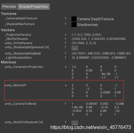
嗯,它就是个简单的正交投影,目的就是让变换后的顶点xy都在视锥体的边界( ? w ≤ x ≤ w , ? w ≤ y ≤ w -w \leq x \leq w, -w \leq y \leq w ?w≤x≤w,?w≤y≤w??),这么做是为了方便后面的计算。
往下看,clipPos.y乘上了一个_ProjectionParams.x的分量,它表示投影矩阵是否经过翻转。1就是没有翻转,-1就是翻转过。这个分量主要是用来处理camera渲染到render texutre的平台差异的。众所周知,DirectX的uv坐标系是顶点在左上角,v方向竖直向下;而OpenGL是顶点在左下角,v方向竖直向上:
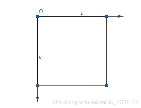
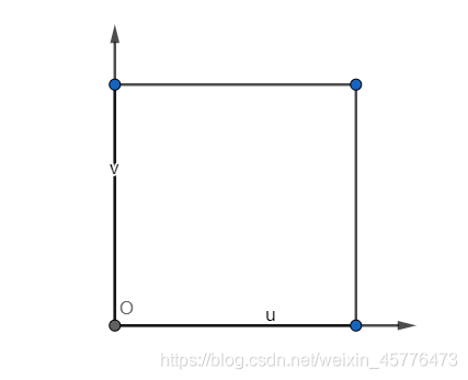
通过翻转投影矩阵,可以在渲染render texture时,不用关心平台差异,从0到1按OpenGL的规范渲染即可。这里对clipPos.y去手动乘以这个分量也是类似的原因,保证clipPos.y是符合OpenGL的规范的。
接下来就是逆投影变换,把剪裁空间的点变换到相机空间,求出近远剪裁面的坐标。这里使用了unity_CameraInvProjection而不是UNITY_MATRIX_P的逆矩阵,表示我们不关心平台细节,直接按照OpenGL规范进行逆投影变换,并且这里的camera指的主相机而不是当前相机,而我们之前已经处理过clipPos,因此直接计算即可。
最后对求出的orthoPosNear,orthoPosFar的z分量乘以-1,是因为在OpenGL规范中相机空间的z都是负数,再次取负变成正的z,方便后面计算。
frag_hard
fragement shader根据是否启用软阴影,有frag_hard和frag_pcfSoft两套实现。先看下frag_hard:
fixed4 frag_hard (v2f i) : SV_Target
{
    float4 wpos;
    float3 vpos;

    vpos = computeCameraSpacePosFromDepth(i);
    wpos = mul (unity_CameraToWorld, float4(vpos,1));

    fixed4 cascadeWeights = GET_CASCADE_WEIGHTS (wpos, vpos.z);
    float4 shadowCoord = GET_SHADOW_COORDINATES(wpos, cascadeWeights);

    //1 tap hard shadow
    fixed shadow = UNITY_SAMPLE_SHADOW(_ShadowMapTexture, shadowCoord);
    shadow = lerp(_LightShadowData.r, 1.0, shadow);

    fixed4 res = shadow;
    return res;
}
代码看起来通俗易懂,这里就不解释了,让我们看看里面用到的几个函数。computeCameraSpacePosFromDepth顾名思义就是计算当前pixel在相机空间中的位置,它有两套不同的实现方式,一种是unity_CameraInvProjection矩阵逆投影变换,还有一种是计算出当前pixel在相机空间的深度,手动插值计算:
/**
* Get camera space coord from depth and inv projection matrices
*/
inline float3 computeCameraSpacePosFromDepthAndInvProjMat(v2f i)
{
    float zdepth = SAMPLE_DEPTH_TEXTURE(_CameraDepthTexture, i.uv.xy);

    #if defined(UNITY_REVERSED_Z)
        zdepth = 1 - zdepth;
    #endif

    // View position calculation for oblique clipped projection case.
    // this will not be as precise nor as fast as the other method
    // (which computes it from interpolated ray & depth) but will work
    // with funky projections.
    float4 clipPos = float4(i.uv.zw, zdepth, 1.0);
    clipPos.xyz = 2.0f * clipPos.xyz - 1.0f;
    float4 camPos = mul(unity_CameraInvProjection, clipPos);
    camPos.xyz /= camPos.w;
    camPos.z *= -1;
    return camPos.xyz;
}

/**
* Get camera space coord from depth and info from VS
*/
inline float3 computeCameraSpacePosFromDepthAndVSInfo(v2f i)
{
    float zdepth = SAMPLE_DEPTH_TEXTURE(_CameraDepthTexture, i.uv.xy);

    // 0..1 linear depth, 0 at camera, 1 at far plane.
    float depth = lerp(Linear01Depth(zdepth), zdepth, unity_OrthoParams.w);
#if defined(UNITY_REVERSED_Z)
    zdepth = 1 - zdepth;
#endif

    // view position calculation for perspective & ortho cases
    float3 vposPersp = i.ray * depth;
    float3 vposOrtho = lerp(i.orthoPosNear, i.orthoPosFar, zdepth);
    // pick the perspective or ortho position as needed
    float3 camPos = lerp(vposPersp, vposOrtho, unity_OrthoParams.w);
    return camPos.xyz;
}
GET_CASCADE_WEIGHTS宏根据是否定义SHADOWS_SPLIT_SPHERES关键字也有两套实现。这个关键字取决于前文提到quality settings中的Shadow Projection设置,只有设置为Stable Fit时该关键字才会启用。先看下没有定义该关键字,也就是Close Fit的情况:
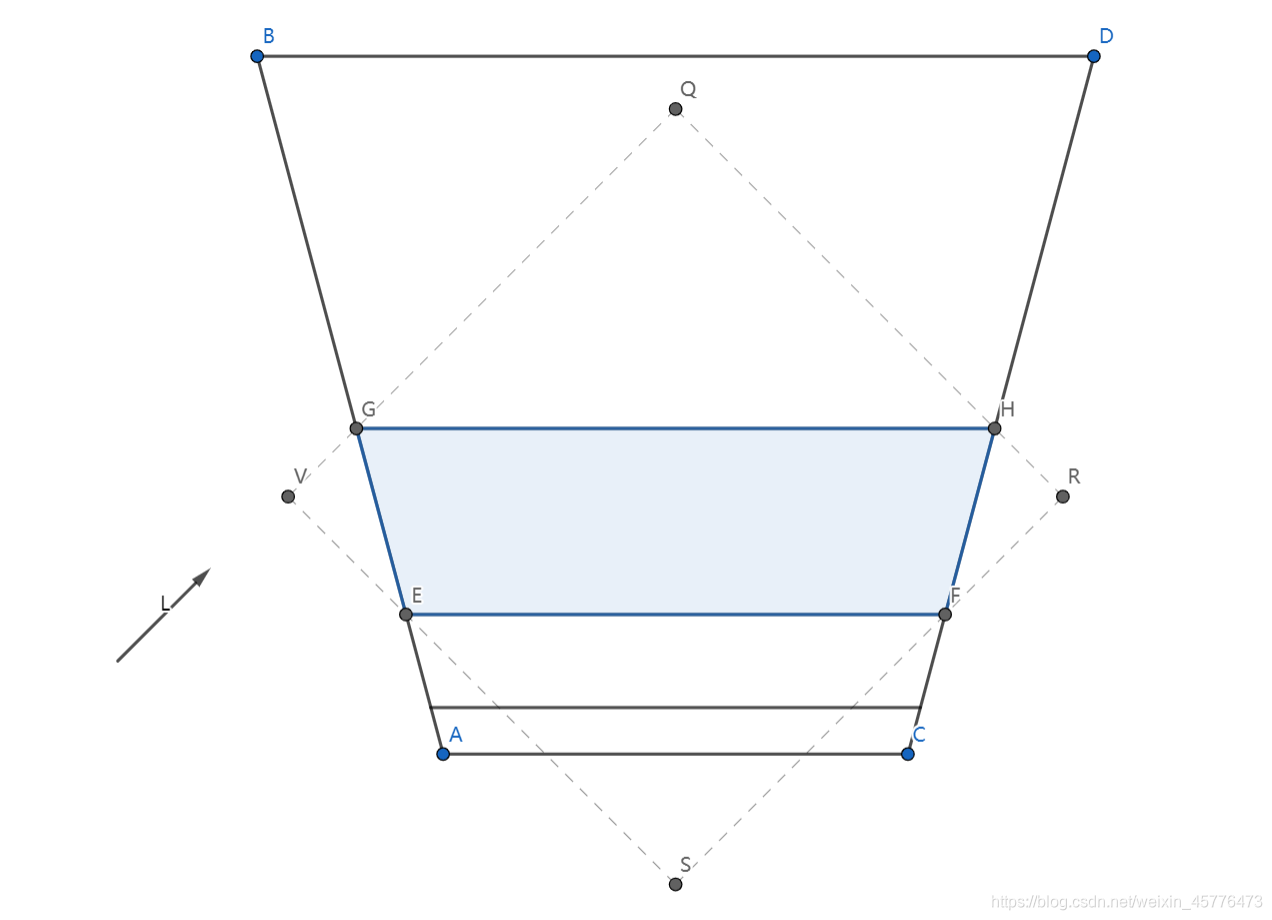
Close Fit的原理如图所示,根据相机距离的远近划分视锥体,对每个子视锥体计算其包围盒,该包围盒就是光源相机的视锥体。
/**
 * Gets the cascade weights based on the world position of the fragment.
 * Returns a float4 with only one component set that corresponds to the appropriate cascade.
 */
inline fixed4 getCascadeWeights(float3 wpos, float z)
{
    fixed4 zNear = float4( z >= _LightSplitsNear );
    fixed4 zFar = float4( z < _LightSplitsFar );
    fixed4 weights = zNear * zFar;
    return weights;
}
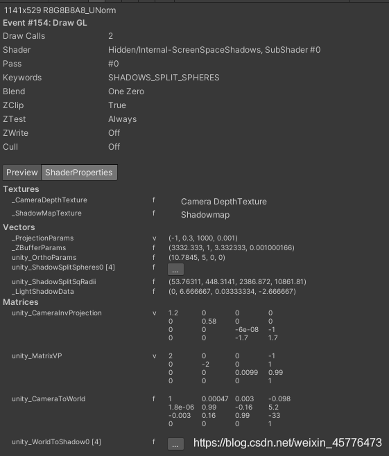
函数接受两个参数,wpos是顶点的世界坐标,z是其在相机空间中的深度。这里的z遵循深度值越大,离相机越远的规则。代码很简单,就是计算当前坐标位于哪个cascade中。用frame debug确认下具体的参数细节:

主相机的近剪裁面距离是0.3,远剪裁面距离是1000,但我们还设置了shadow distance为200,意味着200之后就不再有阴影了,所以这里可以就把shadow distance认为是远剪裁面的距离。cascade splits设置为6.7%,13.3%,26.7%,53.3%,这表示划分后4个子视锥体的大小。那么_LightSplitsNear和_LightSplitsFar就是保存4个子视锥体的近剪裁面和远剪裁面距离。计算公式如下:
n
i
=
{
N
,
i
=
0
f
i
?
1
,
i
>
0
n_i = \left\{ \begin{aligned} N, i = 0 \\ f_{i-1}, i > 0 \\ \end{aligned} \right. \\
ni?={N,i=0fi?1?,i>0?
f
i
=
n
i
+
(
F
?
N
)
?
p
f_i = n_i + (F - N) \cdot p
fi?=ni?+(F?N)?p
其中N,F就是近远剪裁面的距离,p是分割比例,代入计算后的结果就是_LightSplitsNear和_LightSplitsFar的值。
再看一下Stable Fit的情况,Stable Fit是用包围球的方式对视锥体进行划分的:
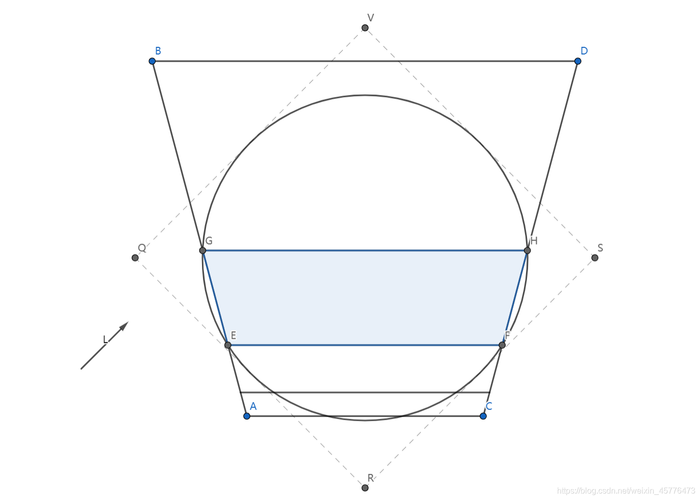
我们在前文中提过,Stable Fit模式下的阴影不会受摄像机自身的位置和旋转影响,这里通过两张图我们可以发现,Close Fit时光源相机视锥体的大小会随着光源方向变化,而Stable Fit却不会。光源视锥体大小变化意味着生成的shadow map分辨率会发生变化,从而产生一种称为阴影边缘闪烁的瑕疵。
/**
 * Gets the cascade weights based on the world position of the fragment and the poisitions of the split spheres for each cascade.
 * Returns a float4 with only one component set that corresponds to the appropriate cascade.
 */
inline fixed4 getCascadeWeights_splitSpheres(float3 wpos)
{
    float3 fromCenter0 = wpos.xyz - unity_ShadowSplitSpheres[0].xyz;
    float3 fromCenter1 = wpos.xyz - unity_ShadowSplitSpheres[1].xyz;
    float3 fromCenter2 = wpos.xyz - unity_ShadowSplitSpheres[2].xyz;
    float3 fromCenter3 = wpos.xyz - unity_ShadowSplitSpheres[3].xyz;
    float4 distances2 = float4(dot(fromCenter0,fromCenter0), dot(fromCenter1,fromCenter1), dot(fromCenter2,fromCenter2), dot(fromCenter3,fromCenter3));
    fixed4 weights = float4(distances2 < unity_ShadowSplitSqRadii);
    weights.yzw = saturate(weights.yzw - weights.xyz);
    return weights;
}
函数计算当前顶点与4个包围球的距离,unity_ShadowSplitSpheres就是4个包围球的世界坐标,unity_ShadowSplitSqRadii就是4个包围球的半径平方。由于包围球可能两两之间有交集,一个点可能位于交集之中,Unity对这种情况进行了处理,确保顶点只属于某一个包围球。同样可以使用frame debug看到具体的细节:
然后我们继续看代码,GET_SHADOW_COORDINATES宏也有两套不同的实现,取决于是否定义SHADOWS_SINGLE_CASCADE关键字。这个关键字表示在Shadow Projection设置中cascade的数量,如果设置为No Cascades则会定义该关键字。这种情况下的函数实现非常简单:
/**
 * Same as the getShadowCoord; but optimized for single cascade
 */
inline float4 getShadowCoord_SingleCascade( float4 wpos )
{
    return float4( mul (unity_WorldToShadow[0], wpos).xyz, 0);
}
对于使用cascade的情况,函数定义如下:
/**
 * Returns the shadowmap coordinates for the given fragment based on the world position and z-depth.
 * These coordinates belong to the shadowmap atlas that contains the maps for all cascades.
 */
inline float4 getShadowCoord( float4 wpos, fixed4 cascadeWeights )
{
    float3 sc0 = mul (unity_WorldToShadow[0], wpos).xyz;
    float3 sc1 = mul (unity_WorldToShadow[1], wpos).xyz;
    float3 sc2 = mul (unity_WorldToShadow[2], wpos).xyz;
    float3 sc3 = mul (unity_WorldToShadow[3], wpos).xyz;
    float4 shadowMapCoordinate = float4(sc0 * cascadeWeights[0] + sc1 * cascadeWeights[1] + sc2 * cascadeWeights[2] + sc3 * cascadeWeights[3], 1);
#if defined(UNITY_REVERSED_Z)
    float  noCascadeWeights = 1 - dot(cascadeWeights, float4(1, 1, 1, 1));
    shadowMapCoordinate.z += noCascadeWeights;
#endif
    return shadowMapCoordinate;
}
cascadeWeights是一个四维向量,最多只有一个维度的值为1。当cascadeWeights是零向量时,即顶点不在阴影中,需要考虑下reverse z的情况,因为此时计算出的shadowMapCoordinate的z分量是0。
frag_pcfSoft
这样一来,我们就只剩下软阴影的代码还没看了:
/**
 *  Soft Shadow (SM 3.0)
 */
fixed4 frag_pcfSoft(v2f i) : SV_Target
{
    float4 wpos;
    float3 vpos;

    vpos = computeCameraSpacePosFromDepth(i);
    // sample the cascade the pixel belongs to
    wpos = mul(unity_CameraToWorld, float4(vpos,1));

    fixed4 cascadeWeights = GET_CASCADE_WEIGHTS(wpos, vpos.z);
    float4 coord = GET_SHADOW_COORDINATES(wpos, cascadeWeights);

    float3 receiverPlaneDepthBias = 0.0;
#ifdef UNITY_USE_RECEIVER_PLANE_BIAS
    // Reveiver plane depth bias: need to calculate it based on shadow coordinate
    // as it would be in first cascade; otherwise derivatives
    // at cascade boundaries will be all wrong. So compute
    // it from cascade 0 UV, and scale based on which cascade we're in.
    float3 coordCascade0 = getShadowCoord_SingleCascade(wpos);
    float biasMultiply = dot(cascadeWeights,unity_ShadowCascadeScales);
    receiverPlaneDepthBias = UnityGetReceiverPlaneDepthBias(coordCascade0.xyz, biasMultiply);
#endif

#if defined(SHADER_API_MOBILE)
    half shadow = UnitySampleShadowmap_PCF5x5(coord, receiverPlaneDepthBias);
#else
    half shadow = UnitySampleShadowmap_PCF7x7(coord, receiverPlaneDepthBias);
#endif
    shadow = lerp(_LightShadowData.r, 1.0f, shadow);

    // Blend between shadow cascades if enabled
    //
    // Not working yet with split spheres, and no need when 1 cascade
#if UNITY_USE_CASCADE_BLENDING && !defined(SHADOWS_SPLIT_SPHERES) && !defined(SHADOWS_SINGLE_CASCADE)
    half4 z4 = (float4(vpos.z,vpos.z,vpos.z,vpos.z) - _LightSplitsNear) / (_LightSplitsFar - _LightSplitsNear);
    half alpha = dot(z4 * cascadeWeights, half4(1,1,1,1));

    UNITY_BRANCH
        if (alpha > 1 - UNITY_CASCADE_BLEND_DISTANCE)
        {
            // get alpha to 0..1 range over the blend distance
            alpha = (alpha - (1 - UNITY_CASCADE_BLEND_DISTANCE)) / UNITY_CASCADE_BLEND_DISTANCE;

            // sample next cascade
            cascadeWeights = fixed4(0, cascadeWeights.xyz);
            coord = GET_SHADOW_COORDINATES(wpos, cascadeWeights);

#ifdef UNITY_USE_RECEIVER_PLANE_BIAS
            biasMultiply = dot(cascadeWeights,unity_ShadowCascadeScales);
            receiverPlaneDepthBias = UnityGetReceiverPlaneDepthBias(coordCascade0.xyz, biasMultiply);
#endif

            half shadowNextCascade = UnitySampleShadowmap_PCF3x3(coord, receiverPlaneDepthBias);
            shadowNextCascade = lerp(_LightShadowData.r, 1.0f, shadowNextCascade);
            shadow = lerp(shadow, shadowNextCascade, alpha);
        }
#endif

    return shadow;
}
代码基本是自明的,同硬阴影类似,首先计算出当前pixel的相机空间坐标和世界坐标,然后转换到阴影空间求得其阴影剪裁空间坐标。根据是否启用bias,调用前文提到过的UnityGetReceiverPlaneDepthBias计算bias,然后对shadow map进行采样,如果是移动平台,则使用PCF5x5的方式进行采样,否则使用PCF7x7。这两者的实现方式与前文提到过的UnitySampleShadowmap_PCF3x3类似,都是使用等腰三角形进行面积覆盖,计算出不同采样点的权重。只不过5x5需要采样9次,用到的等腰三角形长为5个texel,高为2.5个texel;7x7需要采样16次,用到的等腰三角形长为7个texel,高为3.5个texel。
由于当前pixel可能是位于两个不同的cascade边界附近,因此可以对采样的结果再做一次blend操作。我们直接对cascadeWeights向量做一次右移操作即可得到下一个cascade对应的weights向量,然后拿这个向量再计算一次当前pixel的阴影剪裁空间坐标,去采样shadowmap。这样就可以对两个cascade下shadowmap的采样结果进行blend,blend的权重就是当前pixe到所属cascade近剪裁面的距离。
本系列文章所有的参考如下:
Reference
[1] Shadows
[3] 自适应Shadow Bias算法
[5] UWA问答
[6] Unity实时阴影实现――Screen Space Shadow Mapping
[7] SampleCmp (DirectX HLSL Texture Object)
[8] what is in float4 _LightShadowData?
[9] An introduction to shader derivative functions
[10] Shadow Mapping: GPU-based Tips and Techniques
[11] 阴影的PCF采样优化算法
[12] 把float编码到RGBA8
[13] CubeMap采样过程
[14] Unity实时阴影实现――Cascaded Shadow Mapping
[15] Cascade Shadow进阶之路
[16] 关于ComputeScreenPos和ComputeGrabScreenPos的差别
[17] What’s difference between UNITY_MATRIX_P and unity_CameraProjection?
如果你觉得我的文章有帮助,欢迎关注我的微信公众号(大龄社畜的游戏开发之路)